technical diversions

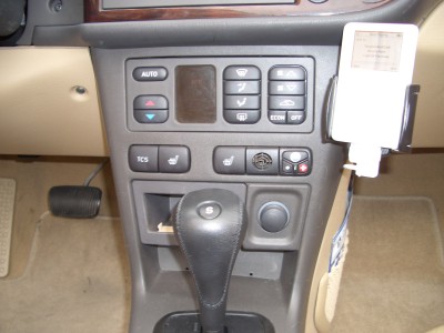
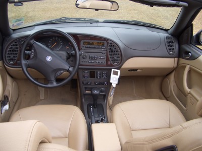
a place to document my current project of connecting an iPod to a Saab 9-3 convertible with the factory audio system.

Monday, September 11, 2006

this may explain some strange results...

For some people the much more simple modification described by Seth works very good, but for some people it does not work, or stops working after some time. I have not researched on this and I now mostly enjoy my iPod but to give another example of the power of a network I will post an e-mail that I got from Arne that probably explains what is going on. Here is his e-mail:

Hello All,

Although I have not created an AUX input yet, I plan to and studied all the descriptions from all of you in advance.

Just studied my 9-3 2001 radio unit (newer type PU-2135C) a bit and have some remarks.

Did some PCB tracing and reverse engineering:
The TEL and CD inputs are DC separated by 10 uF/16V and buffered by an op-amp before it is fed to the pre-amp (the point on the PCB where the two TEL inputs are connected together)

Using a NJM2058 from op-amp from JRC they have created a differential TEL input, the CD inputs are just a 1x op-amp. There is also a 1K series+1K to ground attenuator at the input of TEL+

This does explain the lower volume on the unmodified TEL input.

And this could also explain why Seth's simple mod (soldering an input socket directly to the pre-amp) can damage your radio. Because you bypass the DC separation and buffering, a peak or static discharge could damage the pre-amp input.

I think that simply adding a electrolytic capacitor of 10 uF (minus towards signal source) in the L and R line and maybe a 100 Ohm series resistor should be added to make this mod less "dangerous".

Re-routing the CD inputs like German does is the safest way if you don't use the CD changer.

Currently I only added a 60 mm CPU fan to the back of the radio unit because the front and CD's became very hot after an hour !
When this mod proves successful, I plan to do some more testing on the TEL input.


Greetings,
Arne
The Netherlands


Arne, thank you very much for sharing this research!

-- German Alvarez
Tuesday, March 28, 2006

A radio mod from Ad

Some time ago Ad from the Netherlands asked me for the schematics and some other info to develop a solution for his MPG-3 player. With the spring, when he found his car under the snow, he completed his project and here is the document he sent me:

http://gatoalfa.calipso.com.co/radioMod/contrib/Saab-radio-mod-AHS.pdf

Is a great project, it combines and greatly expands some ideas from Seth and some from me. Ad also agreed to let me post here his e-mail, "a DOT schrijver AT onsnet DOT nu"

Ad says nice thinks about the electronics I'm using to handle the logic; to give credit where credit is due the fundamental design for that building block, as I mentioned before, is from my good friend SQ.

Friday, December 09, 2005

an update!

Long time without an update. I still enjoy driving the saab, but the colder climate has restricted a little the days I ride with the top down. This a fun car to drive!

The iPod keeps getting new music, and it has enabled me to explore new artists and music genres. Before the iPod I added very few song and in general groups to my listening experience and this is changing fast.

I’m very happy that David from Texas decided to give my idea a try and I build for him the little circuit board. He was extremely patient, it took me several weeks to find enough time to complete it, but just after the Thanksgiving holiday I managed to ship him the parts. He got in touch with a technically savvy auto electronics expert and in a few hours had the system up and running. Here are a few pictures of his installation!


Monday, April 25, 2005

How to mod the radio

Many thanks to all the contributors, and the ones that tested this on their cars. After a few ones have done this, i think the document is ready to be posted.

Here is the link to it.

http://gatoalfa.calipso.com.co/radioMod/saabRadioMod.html

This document describes how to add an AUX input to the factory radio. This can be phono stereo 1/8 jack or RCA type. The input will be for a "line level" signal but a signal from the headphone jack of your player will work, just be careful with the volume level. Adding this input uses part of the circuits and connectors used for the external CD changer. After this modification the external CD changer cannot be used (or installed). The modification is reversible.

Seth describes a much simple way to modify the radio on this link:

http://www.sethevans.com/auxinput.html

During the development of my installation I tried to do what Seth did but it did not work for me. I do not know why. An important difference is that he is using the headphone output and i'm using the line level output. This is an open issue and my suggestion is to follow what Seth did and if it works for you, just stop there. If it does not work or you want to keep the onStar/Telephone interface working then you need to go all the way.

Wednesday, February 16, 2005

so you want one? (long post)

Now that i have it working for me i will dedicate some time to document this so other can follow and improve this.

This project can be divided in 3 parts:

1.- Add an AUX input to the factory radio. This can be phono stereo 1/8 jack or RCA type. The input will be for a "line level" signal but a signal from the headphone jack of your player will work, just be careful with the volume level. Adding this input uses part of the circuits and connectors used for the external CD changer. After this modification the external CD changer cannot be used (or installed). The modification is reversible.

2.- by doing part 1 you gain the AUX input, but you no longer can use the onStar/telephone interface in your radio. If you want to keep that functionality then you can use the circuit i designed. This circuit has these features:

* Ads two inputs to the radio, one is designed for the iPod, and the other if for any other audio device. The input is a phone stereo 1/8 jack.

* Keeps the onStar/telephone interface working normally. If there is a call in progress it will override any other input and the telephone signal will be feed to the radio, like the normal operation.

* Has a switch with three positions to control the iPod/AUX input: off, charge only and charge + play

* Small enough to fit inside the saab phone holder.

* Filtered, diode and fuse protected power supply for your iPod

This circuit is designed to use parts from the belkin car adaptor. The parts used are the iPod dock connector & cable and the amplifier. Even if not using the iPod, the amplifier on this adaptor is convenient because the signal level can be adjusted.

The circuit needs to be connected to: +12V accessory power (called +15 in saab terminology), ground, audio&ground from the onStar/telephone, TEL-MUTE signal from the telephone, TEL-MUTE going to the radio, stereo audio signal going to the radio

3.- Physically mounting the iPod. I used the saab phone holder and the belkin iPod carrier, using “pressure sensitive” double sided tape. I had to put three layers of tape on the top part and only one on the bottom part to give some clearance from the console while removing the iPod.


I have a first draft of the instructions for the part 1 ready. If you want to get it, please send me an e-mail. I will ask you for your feedback on this document. Please note that this requires some experience in working with electronics and some special tools. Once some people have done this i will post it here.

For part 2, i have parts to build 3 more circuits; depending on the interest i will probably sell them. I have not figured this out. Having the circuit is just the starting point, you need to mount it, a little plastic box will do it, or inside the saab phone holder. Also you need to wire it to the car, or take it to a car stereo shop to have it installed. Please provide me some input if will be willing to buy it from me, or rather have the schematics.

For part 3, beside some additional pictures i do not plan to do any more.

Sunday, February 13, 2005

it works!

this is awesome!

this works great, sound quality is perfect, looks nice, works fine. sorry i'm leaving, i'm heading now to go across dumbarton bridge with the top off. Details tomorrow... now is my time to enjoy... Setting up some play lists in iTunes... i want to listen the project:pimento version of "peter gun" while driving over the bridge. I will load also "carmina Burana" to test the dynamic range :-)

some eye candy for now... note the "TELEPHONE" in the display while the iPod is playing.


i have 3 more PCBs. This is not an easy modification, but it is very doable. Give me some input, should i turn this into a kit? I do not have the time/inclination to install this on YOUR car buy i can crank instructions detailed enough for a good car hobbyist/car stereo installer to do it. FEEDBACK is APPRECIATED, please e-mail me.

the kit

i just finished building the circuit.

here are some pictures of how the "kit" looks like:


the iPod holder will be attached using double sided tape to the "phone holder" that houses all the interface electronics. On the bottom part is the switch; 3 way for off, charge and charge + play. Also to the left of the switch is the additional AUX-IN to connect any other device.


I finish that late because there was a terrible setback. What follows is very technical, you may want to skip. It looks like when i did the initial testing the oscilloscope was set for AC, and i did not test enough, but the signal at the input for the pre-amplifier is ridding of top of 4VDC (probably to a use single ended power supply on the radio). There are some more details that explain why it initially worked but this problem at 1 AM was a terrible setback. It can be solved technically, probably a few OP-AMPS but that will send the design back to square one and i wanted to finish and close this chapter.

Since the radio interfaces in an analog way to the external CD-changer I decided to test if I can use the signal conditioning used for the CD-changer to adapt the signal form the iPod. A brief test confirmed this, but some additional modifications will have to be performed to the radio. The changes were pretty clear in my mind but decided to wait and get some sleep before doing the surgery. This will also create an additional compromise, the trunk mounted CD-changer will not be usable after modifying the radio. I wanted to think a little bit more before committing to this change.

Next morning I decided to go ahead and modify the radio to use the input stage of the CD-changer to pre-process the signal from the iPod. I do not own the external CD-changer, and in any case the changes are reversible. Some images of the changes here, 1, 2, 3.
As soon as I complete testing i will explain in detail what needs to be done and why.

Friday, February 11, 2005

i have the PCBs

early this morning i received the prototype PCBs, i ordered 4. They look great. It is such a difference, i remember etching my own PCBs with ferric chloride, it was impossible to obtain very clean traces, and do not even think about 2 sided circuit boards. Not only the design, then the etching but then the drilling.

From my computer a few clicks and a credit card i have a very high quality board. Here is a picture of it. I will fit the components today and the hope to complete the project by this weekend.

here is a picture of the board:

Tuesday, February 08, 2005

some clarifications

the onStar system i think is only available in the US. On this document i refer to the onStar interface, but i think the right name to call it is the telephone interface.

The system i'm developing is in fact to use the saab telephone interface to feed the signal. Starting today i will call it telephone interface.

here is what i have to far:

* the saab telephone interface is only monophonic. To feed a stereo signal some modifications have to be done to the radio. check previous postings for this.

* to activate the telephone interface the TEL-MUTE pin has to be connected to ground.

* the electronics i'm developing are to be able to use the iPod, or in fact any audio device, with the telephone interface. The circuit is required to let the actual telephone to override the output in case it becomes active.

* the system will be controlled by a switch with 3 positions: off, iPod charge and charge plus audio from the iPod.

* an additional input (1/8 stereo plug) is available to connect other device like an satellite radio. If something is connected to this plug the iPod will be disabled and the external device will feed the radio.

* to simplify the wiring to the iPod and to have a variable gain amplifier to be able to match the signal level from the iPod, telephone interface and external signal to the radio a belkin car adaptor is used as part of the circuit. Searching for the links for this page i just noticed that belkin has the same car adaptor in black! The black one will go much better with my car interior. By now i will settle with the white one.

* to physically mount the iPod to the car i will use a combination (work in progress) of the saab phone bracket and the belkin iPod holder. The electronics will go inside the saab phone bracket.

PCB layout is done!

Thursday, February 03, 2005

test OK-2 !

ok, then i assembled the circuit on a proto-board and connected it to the car. no smoke, no sparks, it worked perfect!

here is a picture of the connections:


and a close up of the circuit:


the next task is to design the PCB (printed circuit boards) I was thinking originally in just wire it point to point in a generic PCB, but i want it to fit inside the phone holder i got from saab and also the PCBs will make it easier if i want to build a second unit or someone is interested in building one. I may sell the PCBs or even a kit.

here is a picture of the phone holder:


the schematic was created using free software from a company called express pcb. The software works great, and i will create the PCB layout using their software too. They give away the software so you can order PCBs from them. A similar economic model that the one used by front panel express, they give away good CAD software to make it easy for you to get a quote and order from them. I have not used expresspcb yet but have excellent references. I have used front panel express and is difficult to imagine better results.

Wednesday, February 02, 2005

some answers

First, thanks to all of you that have written, it really encourages me to continue. Please share your experiences!

Here are some answers to the more common questions that I have received.

The radio goes into TELEPHONE mode when the MUTE pin is grounded, if you do not have the onStar system this is almost all what you need to know. If you do have the onStar system and want to keep it operational (good idea even if you do not subscribe) then more work is required.

The audio harness and the control harness will go to a circuit that I’m designing with the help of my good friend SQ. It is mostly based on what I posted before.

The circuit will use as a part of it the “guts” of the belkin car adaptor. The adaptor provides the iPod connector and a variable gain amplifier to adjust the signal levels coming from the iPod to the level required by the radio.

The circuit will have a switch that will do normal operation, or activate the input. Additional logic is required to allow the onStar system to override the settings in case it goes active.
As an enhancement I decided to add a second input that can be used for an XM/Sirius radio, a scanner or any other device. Then the final system will have a switch with three positions, iPod, normal, AUX.

The circuit also contains an attenuator to adjust the signal level coming form the onStar system to the lower signal now required.

Here is a link to a preliminary circuit. I assembled that circuit on a proto-board and plan to test it tonight. The output audio output of my circuit goes into the input of the belkin adaptor and then to the radio.

I plan to fit all the circuits inside the cell phone holder that I ordered from the saab catalog. Under that holder I will put the little switch and a 1/8 stereo jack for the second AUX signal.

Tuesday, February 01, 2005

wired

last night i completed wiring the car.

I created to wiring harnesses, one for the power and control signals and another for the audio signal going to the radio.

the control harness:


the audio harness:


here is a view of the car, before installing the power/control harness, the plug that is disconnected is the one that goes to the onStar module. It contains all the signals that i need to get.


and here is a view of the harness connected. It is the one going to the right. All the cables are protected with the braid.


Just the standard disclaimer, do not attempt to do this if you do not have the experience and knowledge. The battery does not have the voltage to shock you but has the current to burn you and burn your car. Also the onStar system receives signals from many systems in you car to alert the control center, including information from the air bags. You can damage many expensive subsystems or have a nasty accident messing with this. This is not a recommendation, just a journal with my own experience. I do not encourage you to follow/copy/imitate anything that i do in my own car. It is a good idea to disconnect the battery before you cut/splice any wire in a car.

Monday, January 31, 2005

got a radio with aux-in!

ok, yesterday i accomplished two things, modify the radio to take the AUX input and wire the car.

I could not find a convenient spot to put a 1/8 stereo jack on the body of the radio then i decided to go with a "pigtail". It was cheaper to buy an "extension cable" with a male and a female 1/8 stereo jack and cut it than to buy the materials.

Here is the pigtail from the back:


And here is inside the radio, cable is routed to the front where if goes under the circuit board:


Here is where the cable is connected. In addition two modifications have to be done to the circuit board, cut a trace between the TEL-R and TEL-L to isolate the channels (the telephone is monophonic) and cut a trace that carried the original signal to the preamplifier.


Then i now have a radio with an AUX input! :-)

Since the car is a hostile environment with a lot of vibration that can wear the insulation of cables it is better to provide additional protection for all the cables. I use an expandable braid that is easy to work with, provides good protection and gives a neat appearance.

Sunday, January 30, 2005

Compromises

doing some final tests today i discovered :-( that the pin 21 remains at 2.25V if the iPod is powered externally. This is really bad news because i con not use it the way i intended to control de radio.

At this point i have two options, use pin 21, or install a switch. I will check with my pillow and hope to have a decision tomorrow.


switchpin 21
good iPod can be docked and still use the radio
iPod can be used with headphones
more generic solution
no switch
bad manual control have to disconnect to listen to the radio/CD


It looks like the switch is the winner! the switch being more generic will also let me put an extra AUX input that i can use for a scanner or other device!

Monday, January 24, 2005

pin 21

pin 21 in the iPod dock connector is the accessory indicator pin, from this link i know that depending on the value of a resistor the iPod will determine the type of dock is in use.

this pin, that is available on the belkin car adaptor, was a reasonable candidate to be used to set the radio into the line-in mode when the iPod is connected; unfortunately using the voltmeter i was never able to find a signal on this pin. I expected it to have some internal resistor connected to Vcc and then with the external one form a voltage divider and the resulting signal read by the iPod.

i was stuck on this paradigm and keep searching for a permanent DC signal on pin 21, but after getting frustrated i decided to use the oscilloscope, and after some time and some luck i found the signal.

Here is it without and additional introduction:


It look like the iPod measures the value of the external resistance measuring how long it takes to discharge an internal capacitor. It performs the measurement once every 20 seconds, and two times in a row after the dock connector is just inserted.
No wonder it was difficult to find this signal!!!

Here is a screen shot of what happens after the dock connector is inserted:


This signal is perfect to switch the radio, it happens when the iPod is initially docked, and every 20s thereafter. It is not present when the iPod is off/sleeping. The only drawback is that the return to normal CD/radio operation will happen a little bit over 20s after the iPod is turned off or disconnected.

Sunday, January 23, 2005

dock connector

i avoid buying from belkin after the unacceptable, for me, trick on their routers to redirect you to an e-commerce site they own every 8 hours; but on this case i had to close my eyes and buy their car docking adaptor. It will really simplify my project providing a nice connector, and a variable gain amplifier to interface to the unknown signal level on the radio.

Here are some pictures of the adaptor.

the connector:


the adaptor:


how to open it:


what is inside:

Thursday, January 20, 2005

mounting the iPod

i just ordered a mounting bracket designed for a cell phone, but convenient to mount the iPod. I also ordered a wiring harness, not sure if i will use it but the less i have to modify the factory wiring the better.

Wednesday, January 19, 2005

second best solution...

Still searching how to detect when the iPod is playing, so the radio can switch to the iPod input.

It looks, after spending "quality time" with the oscilloscope, that there is no easy way to detect on the dock connector when the iPod is active (playing)

I can detect, pin 18 3.3V, when the iPod is docked but the signal is present even if the iPod is off (sleeping). The only bad thing about this is that i will not be able to just recharge the iPod and i.e. listen to the radio/CD. As soon as i put the iPod the radio will switch.

The other problem is that no available cable carries pin 18, i was hoping to use a cable obtained from an adapter like the belkin to avoid dealing with the dock connector.

I will research today if i can use pin 21, accessory indicator to detect the presence of the iPod. Technically it should be possible because the iPod can read the resistance value on that pin to ground to detect the type of docking unit, but it may be a very small signal... the good thig is that that pin is available in the belkin car cable.

ga

Monday, January 17, 2005

searching for the dock connector

:-(
i'm spending much more time than i budgeted just to search for the right iPod connector/cradle and pinout information. It looks like no one produces a connector that has:
1 line-out
2 power to feed the iPod
3 some sort of signal to indicate that the iPod is on

the first two are easy but no cable (yet) provides the third one. The signal is available on the iPod, but again no cable provides that.

At this point i have to options: buy the apple $40 dock and use it for parts, i saw a picture on the web and the connector has all the pins; or buy the belkin iPod adapter and hope that the pin 21 (accessory indicator) can be used to detect the iPod.
This link contains useful information about the belkin unit. Both of them are about the same price.
A third option is do more research, i think i will spend one more day in research for this.

here is a link that contains the most complete set of information (directly or as links) about the iPod dock connector.

the actual interface

with almost all the information, it is now time to start designing the electronics to interface to the radio, or head-unit.

Goals (revised):
* iPod wired interface to the factory radio
* no modifications to the iPod
* as few, and as reversible as possible, modifications to the car
* radio input switching to the iPod when the iPod is active
* onStar phone still usable
* charging the iPod battery


with this very preliminary goals, turned into specifications, my friend SQ designed a circuit that will implement the following logic: (this is the logic, actual voltage levels will be handled by the circuit)


inputsoutputs
onStar activeiPod activeradio TEL-MUTEradio input Lradio input R
000anyany
101onStar audioonStar audio
011iPod audio LiPod audio R
111onStar audioonStar audio


and here is the preliminary circuit. I still need to figure how to detect the iPod presence. This circuit assumes that the iPod announces itself with a +12V signal, i need to research this to adjust the resistors on the circuit for the actual voltage.

Sunday, January 16, 2005

test OK!

today i soldered some cable to what i think is the pre-amplifier input and it worked!!!

it was great to listen to my iPod on the factory radio.


Next:Turn this into a working system.

I consider that all the research needed is done. Next will be:

* install an stereo input jack on the car radio. I think i will use a 1/8 headphone type. Probably a with a de-coupling capacitor for each (L & R) signal.

* a circuit with some logic to feed the iPod or on-star signal to the radio. I want to be able to use the on-star eventually. After talking on the phone with my good friend SQ we have a tentative design!

Saturday, January 15, 2005

stereo (details)

ok, since there is no way to get stereo sound in using the wiring harness i decided to open the radio and see if i can spot the place where the TELEPHONE signal is split to the L & R channel.


after following some traces on the PCBs i found what seems to be the perfect spot!


this looks like the input to the pre-amp, if you look carefully you can see the single trace with the mono signal from the TEL input is split in two the TEL-L and TEL-R.

BTW: this PCB area is located in the main board in the bottom part. To reach it you just need to remove the bottom cover of the radio

as an initial test i used an x-acto knife to cut the PCB trace joining L & R and tested the radio. As expected, the on-star system, played only on the L side :-)

it looks like an interface to the iPod can be as simple as a cable an a switch!

got stereo!

quick update: found the way to feed the stereo signal...

:-)

details in a few minutes... gone testing!

figuring it out

i removed the radio to see if i can find any clues, here is a photo of the label on the top:


some interesting clues here, a "TEL MUTE", "TEL IN", "TEL GND" pins, i hope all are inputs.

Time to get the voltmeter and if it gets complicated then our friend the o-scope!

observations:

* the TEL-MUTE pin shows a 4.76 V, continuously and goes to 0V when the telephone (on-star) is active. Can it be that easy?

* using a set of headphones i monitored the TEL-IN and TEL-GND, looks like a standard analog audio line signal.

things look promising, back to the car...

Friday, January 14, 2005

on-star can help me!

after reading the car manual, i decided i will try to use the on-star input as the input for my iPod.

The main goal is to have a convenient way to play music from the iPod using the existing audio system. To achieve this i also have some set of limitations mostly regarding how much i'm going to alter the car for this. On one end of the scale a nice iPod dock on this car may increase the enjoyment and even the resale value of the car, but also a fried expensive component can be a real drag.

goals:
* iPod docking system, if possible controlled with the steering wheel controls
* as few changes as possible on the car. If possible changes should be reversible
* a short term project... no intention to reverse engineer complicated protocols

observations:
When pressing the blue on-star button the SID displays shows "TELEPHONE", the audio does not sound very well, but I think is an on-star problem and not a radio problem (i hope!). Nice: the radio does not need to be on, this can be nice it the iPod can work with this input.
Sound come from all the speakers, i do not think the on-star has an stereo output, I hope the input on the radio has an L and R channel!

iPod <-> car blues

i bought an iPod a few weeks ago, and i have enjoyed it, so much that now i want to hook it up to the sound system on my car.

I did not want to go the FM-modulator way, and searching on the WEB i could not find any reasonable solution for my car. I have an Saab 9-3 2001 convertible with the factory sound system. I purchased the car, used, a few months ago and other than that nuisance it is a great car.

For my needs the sound system is adequate, i'm not interested in replacing it. The limitation is that it does not have a "line" input, i think newer models have it.

Today on my way home, with the idea of connecting the iPod still running as a background process in my mind, I decided to play with the, for me useless, on-star system that comes factory installed on some of the GM cars.


When i pressed the little blue button and then i heard the "Ready" prompt on the speakers of the radio i had an incredible "ahaaa" moment... can i use this input to feed the audio from my iPod?